UML sequence diagrams are used to show how objects interact in a given situation. The important characteristic of a sequence diagram is that time passes from top to bottom: the interaction starts near the top of the diagram and ends at the bottom (i.e. Lower equals Later).
A popular use for them is to document the dynamics in an object-oriented system. Each key collaboration, diagrams are created that show how objects interact in various representative scenarios for that collaboration.
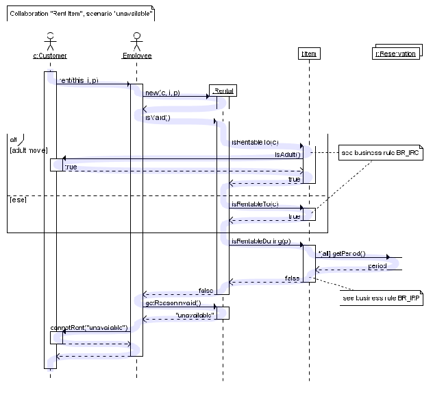
The UML sequence diagram gallery contains many examples, here's a typical sequence diagram based on a system use case scenario:

The diagram above shows how objects interact in the "rent item" collaboration when the item is not available during the requested period.
To clarify how execution switches from one object to another, blue highlight was added to represent the flow of control. This highlight is not part of the diagram itself.
As with all UML diagrams, comments are shown in a rectangle with a folded-over corner:
To relate the comment to whatever diagram elements it is about, to connect them with dashed lines.
Diagram building blocks
If the lifeline is that of an object, demonstrates a role. Leaving the instance name blank can represent anonymous and unnamed instances.
Messages, written with horizontal arrows with the message name written above them, to display interaction. Te solid arrow heads represent synchronous calls, the open arrow heads represent asynchronous messages, the dashed lines represent reply messages. In case if a caller sends a synchronous message, must wait until the message is done, like as invoking a subroutine. In case if a caller sends an asynchronous message, can continue processing and doesn’t have to wait for a response. The Asynchronous calls are present in multithreaded applications and in message-oriented middleware. The activation boxes, method-call boxes, they are opaque rectangles drawn on top of lifelines to represent that processes are being performed in response to the message (ExecutionSpecifications in UML).
Objects calling methods may use messages and add new activation boxes on top of any others to indicate a further level of processing.
When an object is destroyed (removed from memory), X is drawn on top of the lifeline, the dashed line ceases to be drawn below it (this is not the case in the first example though). So it should be the result of a message, from the object itself, and another.
A message sent from the outside diagram can be represented by a message originating from a filled-in circle (found message in UML) or from a border of the sequence diagram (gate in UML).
UML 2 has introduced significant improvements to the capabilities of sequence diagrams. Some of these improvements are based on the idea of interaction fragmentswhich represent smaller pieces of an enclosing interaction. The multiple interaction fragments are combined to create a variety of combined fragments, that are then used to model interactions that include parallelism, the conditional branches, the optional interactions.
OurAssignmentpedia services provide you with a dexterous team of UML sequence diagrams assignment writers and UML sequence diagrams homework helpers and with the unique features it provides will consequently upgrade your results and we assure you of that. Our website provide unique features like
- Original and quality content
- Customized and appropriate format
- 100% confidentiality ensured
- Highly affordable prices
- Always on-time deliveries
- logical and Factual reasoning involved within the content
- 24X7 availability
- No Plagiarism
Our quality and customized format is based on one of the best academic referencing styles including
- Harvard referencing style
- APA referencing style
- Chicago referencing style
- MLA referencing style
And they are built over one of the best journals, articles and research papers.